Falck Schmidt Defence Systems
Finite Element Analyse with full blow!
What happens if we are hit by an explosion? This is essential to know if you are sitting in an armoured crew car or similar. The purpose of this project was to analyse what happens when a structure is hit by a shock wave.
The past 4 years our Finite Element Analysis (FEA) specialist M.Sc. Poul Dürr Pedersen has assisted on a particularly exciting project as sub supplier of simulations for the Danish Defence Materiel Administration (Forsvarets Materielstyrelse).
The main project supplier was a group of specialists in former Falck Schmidt Defence Systems (FSDS). The project was completed under the leadership of Christian Løjtved, Engineering Consulting Corporation (ECC).
In the following we present a summary of how we have used MSC Software SOL700 to replicate physical tests and to gain detailed insight into what happens during detonation of explosives, that propagate as shock waves through the air. As well as what happens when propagation occurs along the ground and when it meets a construction. This could e.g. be a roadside bomb that hit panels on vehicles.
The central parts of the simulation can be schematically illustrated with the following situations, where the purpose is to describe the transient pressure that a construction experiences when exposed to an explosion.
Detonation of explosives and development of shockwave in free expansion
Figure 1: Effects on shock waves propagation along the ground.
Figure 2: Effects of shock waves when it hits a construction.
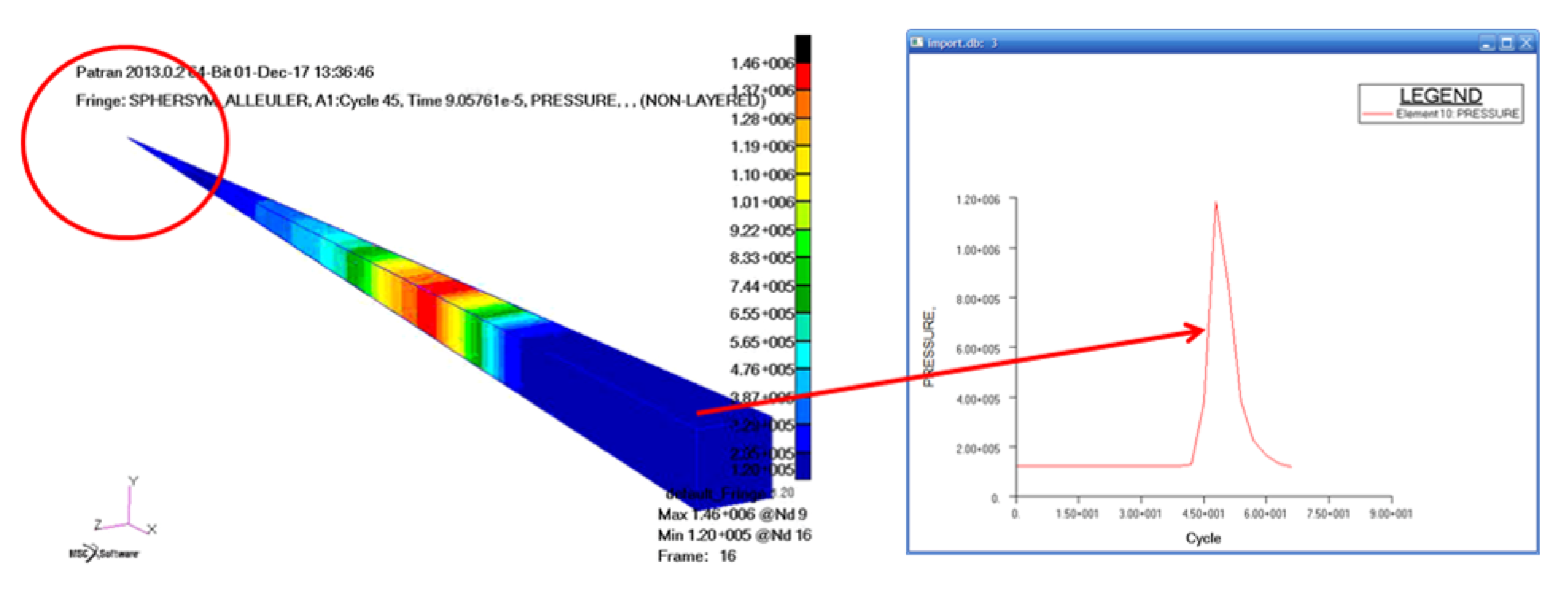
Figure 3: The curves show the transient pressure for many locations along the explosive material.
Initially, detonation of a piece of explosive according to the Jones-Wilkins-Leev (JWL) simulates the state equation for explosives and resulting pressure evolution in the fuel itself.
Figure 4: Simulation in a spherical symmetrical area and Multi Material Euler (MME) liquid method.
A given volume (indicated by red circle) is defined with compressed air which is triggered instantaneously. The curve shows the time for the shock wave to propagate in the air and a transient pressure curve is shown for a point. Curve path and peak value is compare to empirical analytical - terms typically used in this particular industry.
Similarly, in the right representation, the pressure is displayed as the platter structure. As seen there is a considerable increase in the pressure level, if the prevalence of shock waves is prevented.
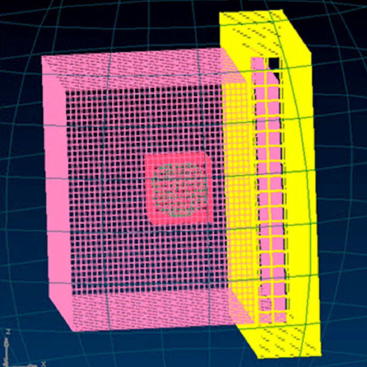
Combining both MME and a Lagrange structure in a Fluid Structure Interaction (FSI) analysis, one can observe the structural response.
Simple tests are performed with explosive blasting close to a steel plate, and the corresponding model is set as a fully coupled analysis with JWL, MME, FSI and non linear material - yet a simple and rough demonstration model.
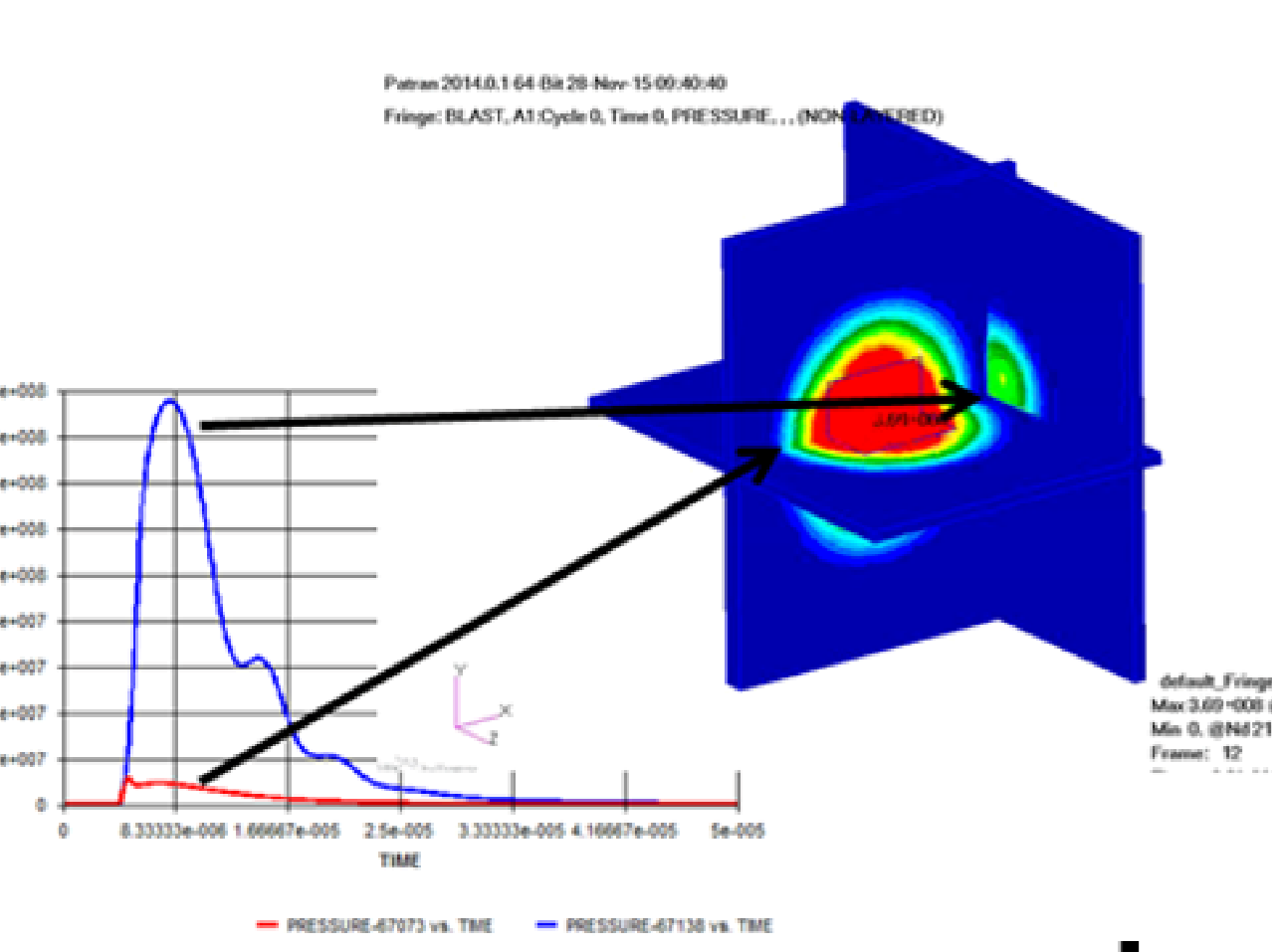
Below, in the left representation are cut sections and curves of the transient pressure for the indicated locations and result extracts in the air domain. The curves represent free expansion (incident pressure, Pinc) and pressure building just in front of the plate (reflected pressure Prefl).
The test in theory and practice
Figure 5:
Figur6 6:
In the left representation are cut sections and curves for the transient pressure for the two indicated locations and result extracts in the air domain. The curves represent free expansion (incident pressure, Pinc) and pressure building just in front of the plate (reflected pressure Prefl).
Figur 7:
Similarly, in the right representation, the pressure that the plate structure experiences is shown. As can be seen from the level, if the shock wave propagation is prevented, there is a considerable increase in the pressure level.
Industrial research reports mention reflection enhancement if the detonated explosive material is raised from the ground - the red dot indicates the definition of triple points.
This phenomenon is demonstrated by an MME analysis and data extraction for every 5 ° and correlated to burst tests where corresponding transient pressure data is collected.
Figure 8:
Industrial research reports mention reflection enhancement if the detonated explosive material is raised from the ground - the red dot indicates the definition of triple points.
This phenomenon is demonstrated by an MME analysis. A data extraction for every 5 ° correlated to burst tests where corresponding transient pressure data is collected.
Figure 9:
ØHHH .... ikke forstået..
Kombineres dette med hårde overflade langs bunden og en barriere i højre kan i et givent domæne, så kan man se begge forstærkningseffekter i samspil.
The use of the FSI technology involves relatively long calculation times, due to very short time steps and large gradients as well as a strong link between fundamentally different domains. Therefore, justifying these heavy calculations can be an industrial challenge, but in this project, it was used to create trust and insight into what is happening, but rationally we had to find a balanced compromise.
Therefore, we ended up using a more empirical analytical implementation (PLBLAST), which is based on a huge test work with roots right back to 1946.
This application obviates the actual calculation of the fluid domain, but describes the transient pressure of each element contained in a coupled surface exposed to the pressure. The pressure load is quickly dissolved in comparison to the FSI model.
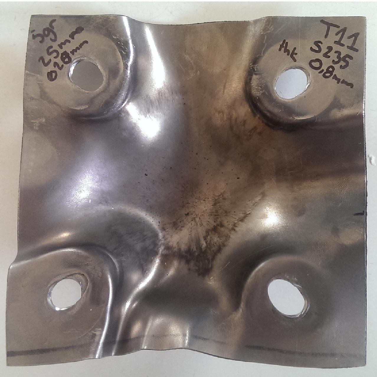
Here are a few examples of steel plates exposed to a detonated explosive mass from different distances and animated results for simulations of similar arrangements.
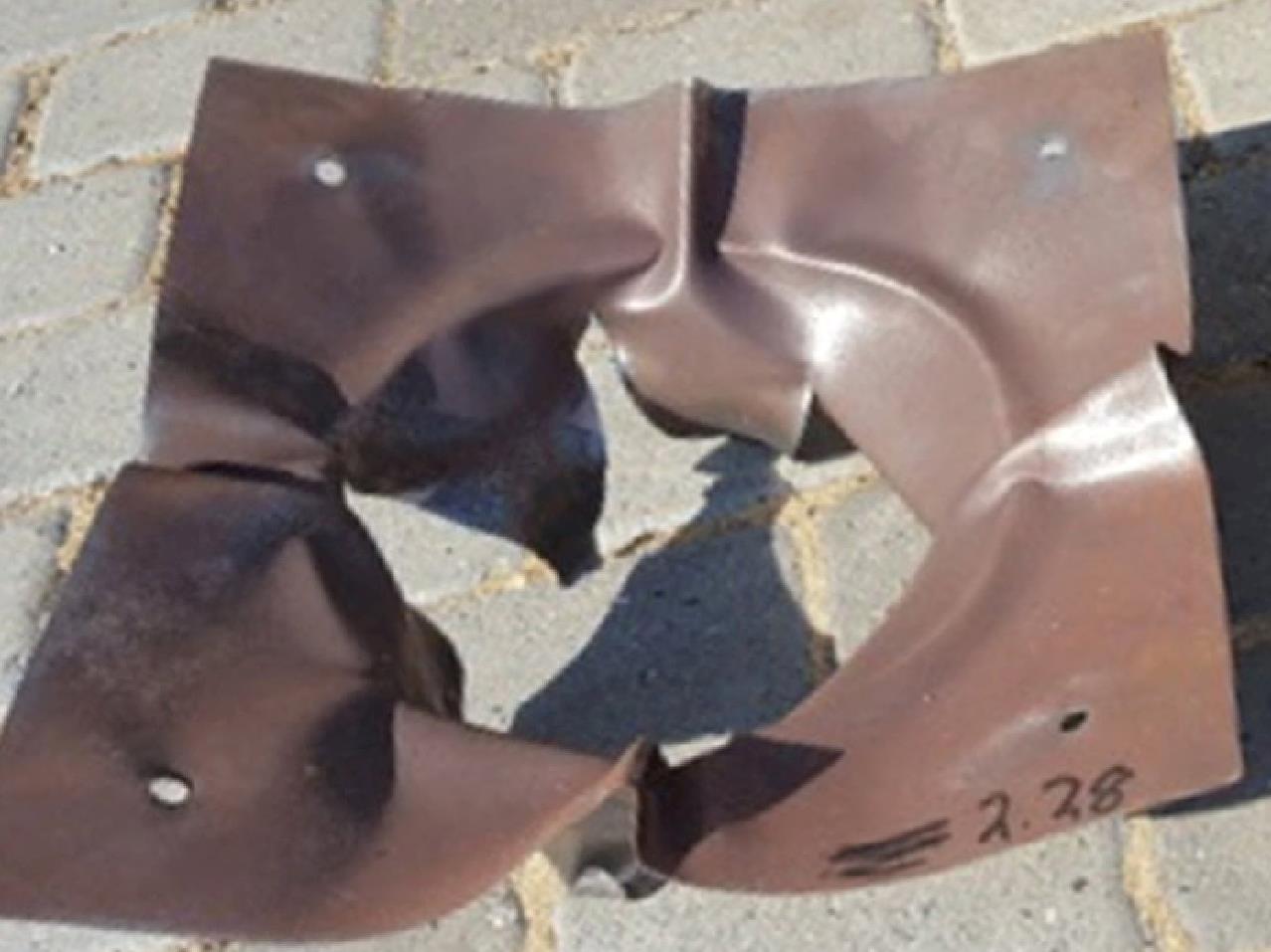
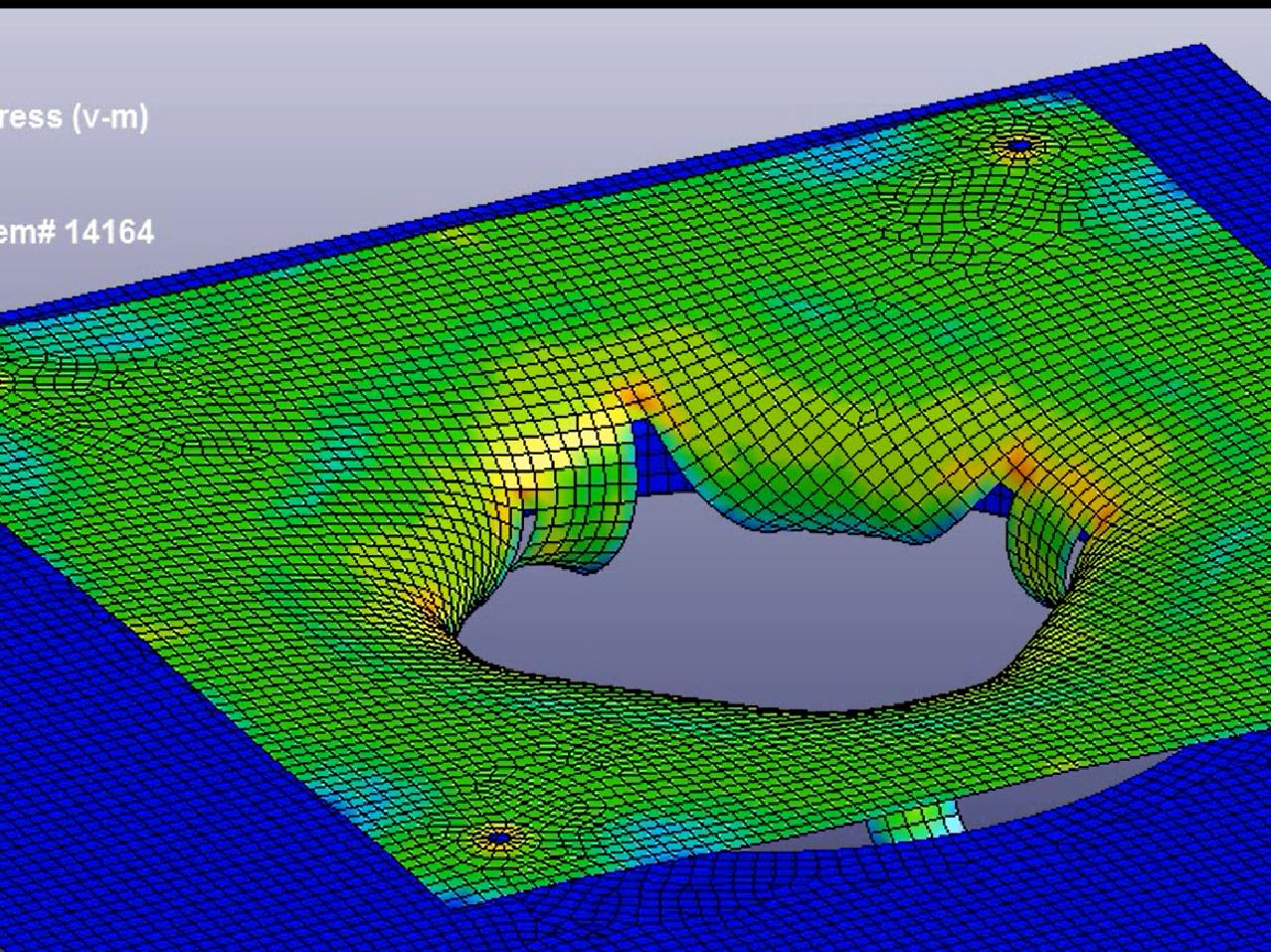
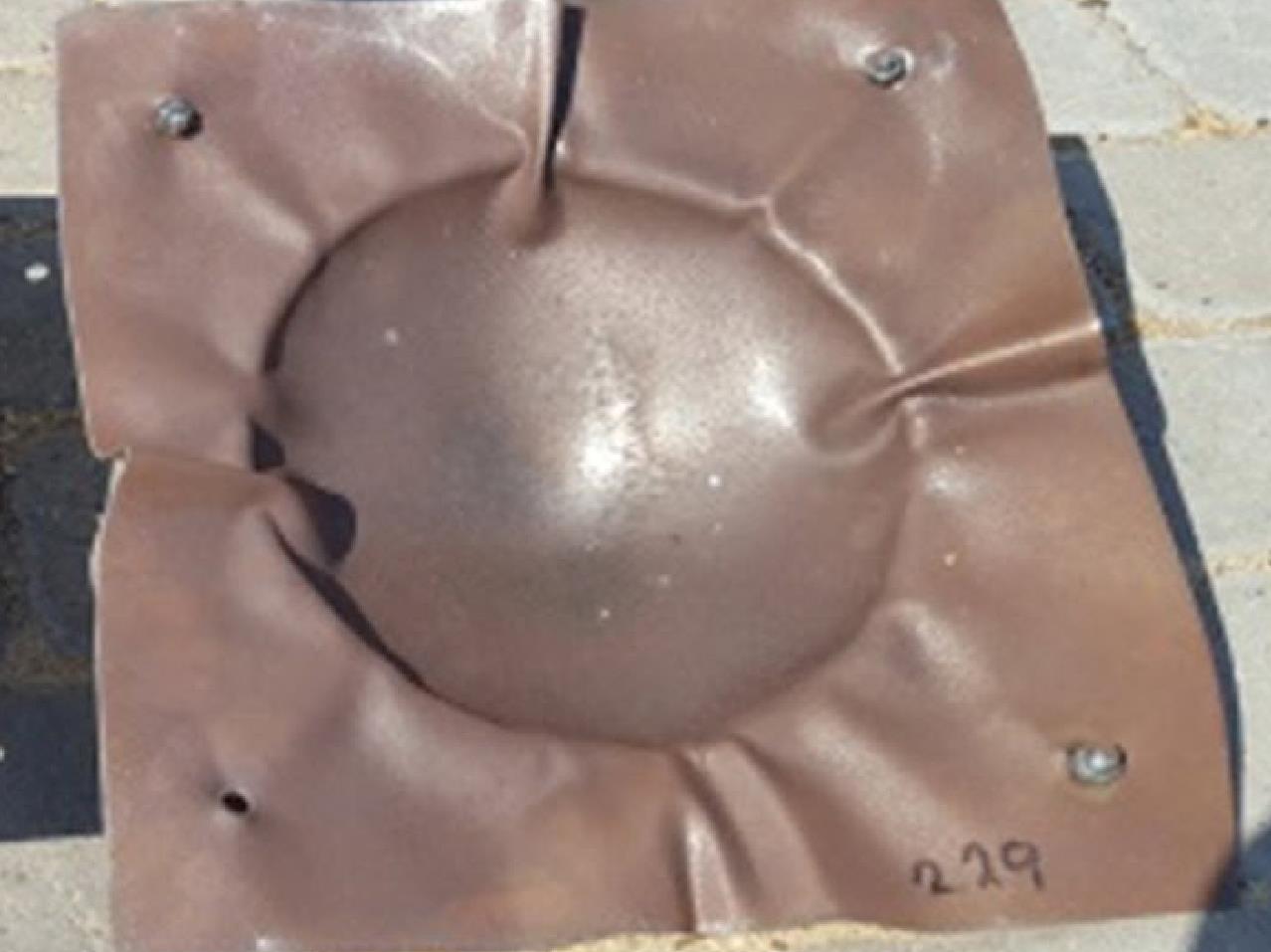
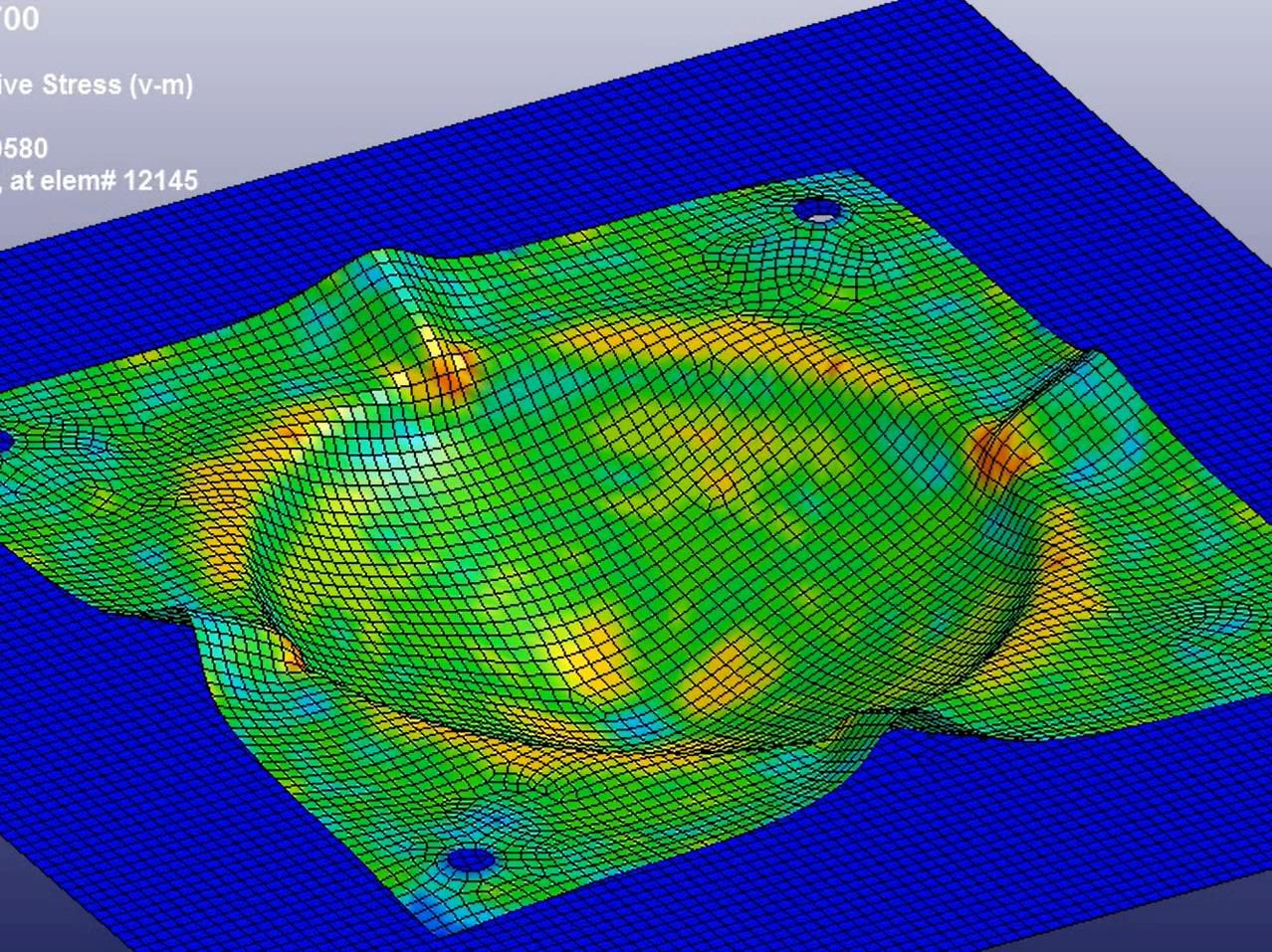
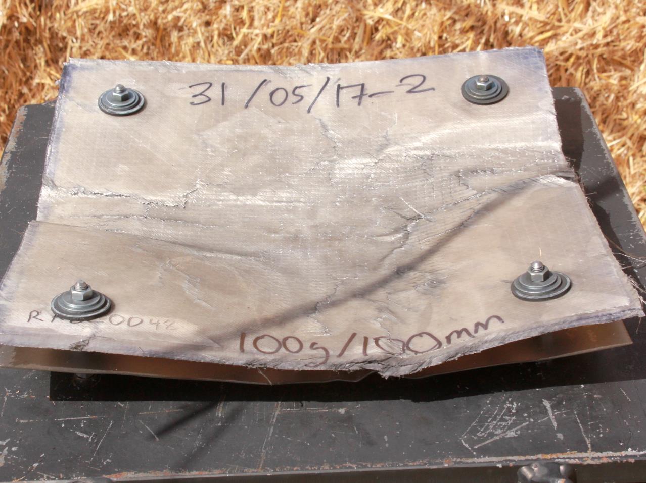
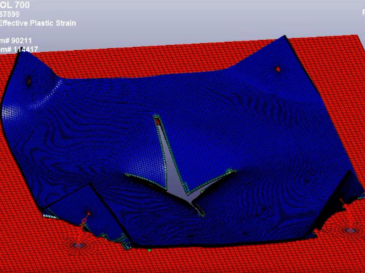
The next step is to replace the relatively simple model of the thin sheet metal (must be elements, isotropic and homogeneous material) with a relatively advanced model for a layered composite sheet (solid elements for each layer, orthotropic materials in different orientations, the layers are held together with a breakable glue formulation), yes the model will be considerably heavier to calculate.
Nevertheless, we achieved good results in macroscopic correlation with blasting tests performed on the corresponding composite sheet blanks.
The engineers behind this case
Contact regarding Engineering Simulation:
Poul Dürr Pedersen has +5 years Aerospace Background within FEA and Airworthiness Certification and composites materials, design, analysis, manufacturing, QA and optimization/automation of engineering processes.
Contact SimEvolution for more information.
Contact regarding the project:
Contact Christian Løjtved, CEO, Engineering Consulting Corporation. ECC@Loejtved.com, phone: +45 21 19 13 01.


Please call me up!
Leave your details and we will call you back as soon as we can.