What is Finite Element Analysis?
– and how to benefit from it!
In development of mechanical products, the designers and engineers can greatly benefit from conducting Finite Element Analysis (FEA) to estimate if the product designed will break, wear out or in other ways not behave as intended.
This is done using the Finite Element Method, FEM, which breaks down e.g. a CAD design into many but finite number of small mathematical elements and simple problem definitions that can be solved efficiently using computational power.
When formulating an applied boundary condition like constraint and loading, all the small solutions add up to an approximate solution to the complex problem in question.
Results can be e.g. deformations of a structure, stresses occurring in the material, response to vibrations or even how the pressure, speed or temperature varies in a flow field around the product design just to mention a few examples.
The results from a finite element analysis can help mechanical designers and engineers to evaluate design variations virtual and quickly and cheap compared to a manufacturing prototypes and subsequent trial and error. Thereby enable a fact based decision making in many mechanical design development projects.
Examples of FE models – Selecting the right level of detail
In preparation of a FE-model one need to be aware of the model detail level, associated advantages as well as disadvantages.
Following is a simple example that walks through modelling of a simple supported IPE200-beam of length 2500mm and subject to uniform pressure of 1MPa (or q=100N/mm).
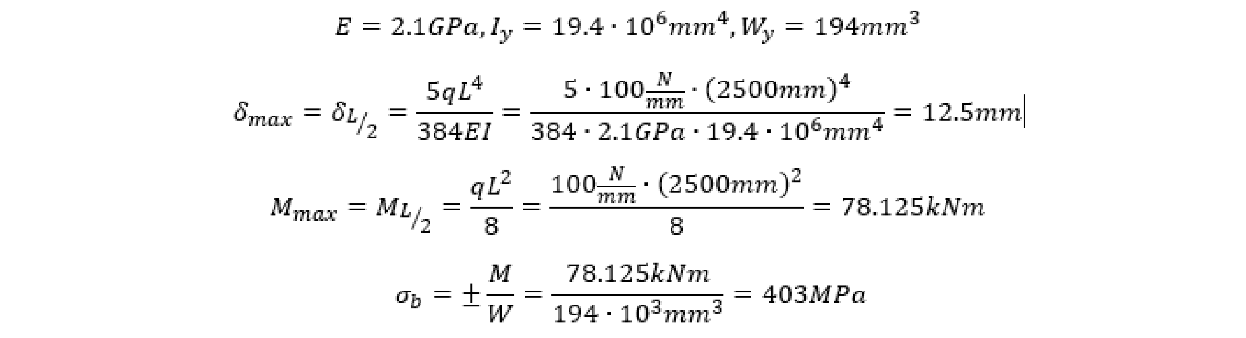
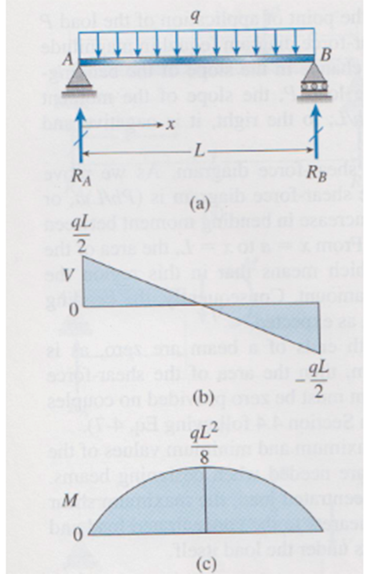
That is max bending occurs at the center and one can use the Timoshenko closed form hand calculation to give a rough idea of the expected response using the steel properties and table figures from e.g. Maskinståbi, where E is steel stiffness, I is area moment of inertia and W is the section modulus:
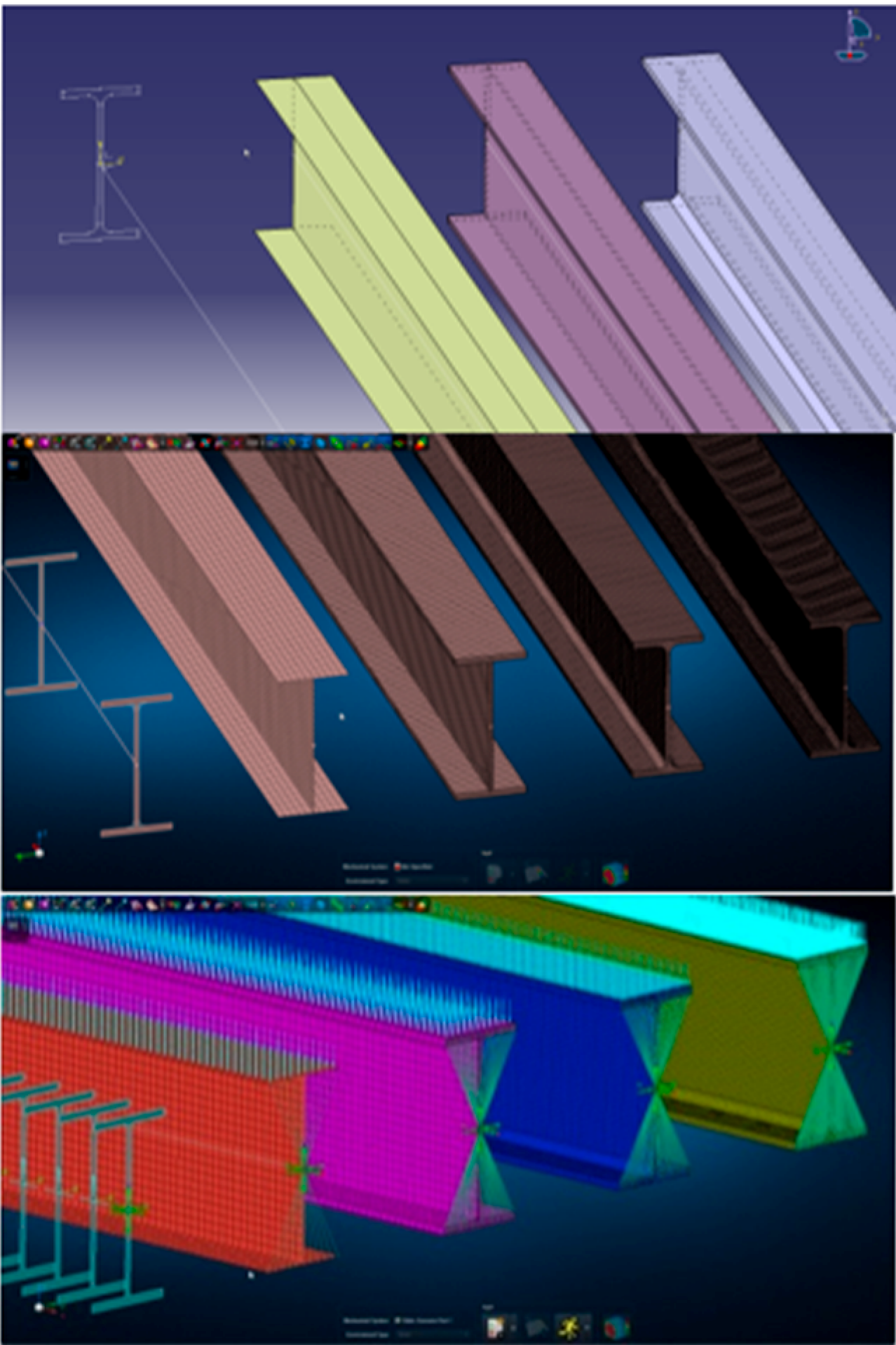
A total of five parallel versions of the beams are setup and discussed in the following:
- 1-D beam elements are simply a discretization of wireframe geometry. Each element refers to both material and a definition of the cross section properties in result of cross section table values. Simply and quickly to modify or optimize but can only provide results as centroid deflection and stress recovery at pre-defined locations e.g . the profile corners / outermost flange.
- 2D shell elements represent the actual beam geometry in terms of the midsurfaces of the profile and each element refer to both material and a thickness. It may take an effort to derive midsurfaces if the origin is solid geometry. However, simple to modify the web and flange thickness separately for initial optimization purposes. The shell models provide excellent deflection of the representation (both web and flanges) and the stress recovery enables a strong insight of stress contours and components.
- 2½D solid elements are represented as hexagons but requires simple geometry, basically a 6 sided box-like or some-kind of extrusion, and therefore may require some degree of modelling preparation skills to support this. However, doing this, one can get a 3D through thickness deflections and a complete stress field.
- Complex 3D solid elements are represented with the tetrahedrons and can model virtually any arbitrary geometry but at the expense of significant increase in model size. That is the total number of Degrees Of Freedom for the mathematical representation that can result in reliable stress recovery results. The result however is very accurate and often the preferred in detailed areas subject to fatigue calculations.
NB! Important to mention that four-noded TETs (as well as three-noded triangular shell elements) behave too stiff and use should be avoided in general and in transition areas only.
Source: Timo Shenko, navn på bog, side...
Drawing from CAD
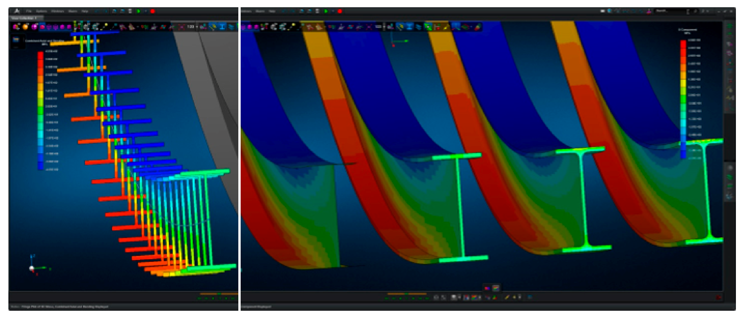
Results of the simulation
What calculation model should be selected?
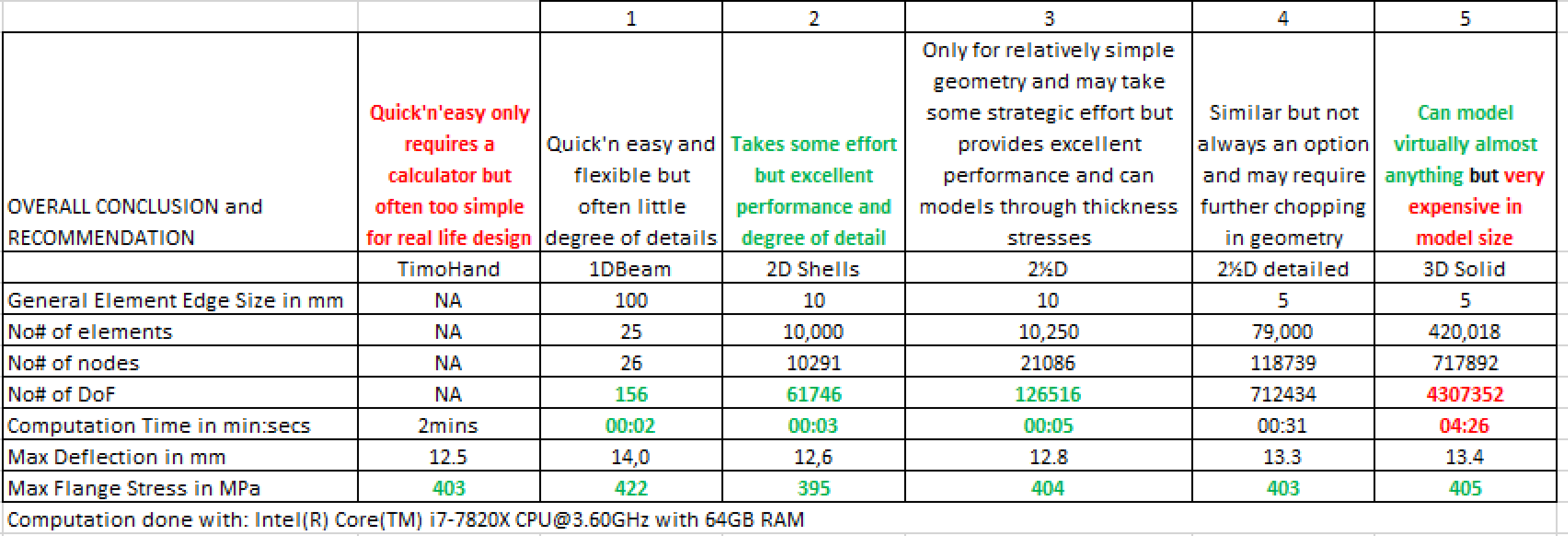
The below table lists the different versions of the beam calculation in terms of the mathematical model size (No# of elements, nodes, and DoFs) with the impact on the corresponding computational expenses and finally with the resulting deflection and bending stresses in comparison.
Conclusion
One can clearly see why a shell representation is the preferred for many structures as considered the best compromise of model details to computational expense – but requires some effort in establishment.
Traditional Process and Advancement
Traditionally, the process is determining the relevant geometry and mesh it to enable a reliable mathematical model including material model assigning the properties. This can be tedious and the accuracy and confidence of the results approximation is often directly dependent on the quality of this effort. Furthermore, the getting the finite element analysis to behave as excepted may be just as tedious.
However, using the right tools can make a large portion of this process easy and fun and with increased computational power; the models can include more and advanced details.
MSC Nastran for Finite Element Analysis
Some of the advanced models can be including non-linearity like contact or material yield and breakage as well as large deformation of rubber-like seal parts. Often non-linear FEA requires some degree of validation to field test to increase confidence.
Going the other direction toward multibody simulation, MBS, the system designer can model the mechanical system behavior and gain insight in how the mechanical components interact and provide estimates on forces acting on each component.
See all the opportunities with MSC One and all the Efficient Tools for Finite Element Analysis
MSC One is a flexible license lease system with access to wide range of applications
MSC Software Applications - get an overview of all the applications delivered by MSC Software
Our Engineering Team
Are you looking for experts in Finite Element Analysis?
Please feel free to contact us.


Please call me up!
Leave your details and we will call you back as soon as we can.